

Controlling LED Strips with Java and JBang
- January 22, 2024
- 7 min read
One of the most "fancy" electronic components is definitely... a LED strip. It’s really cool to control a long strip of lights with only a few lines of code.
But, there is a problem. The timing of the signals is crucial to reliably control these strips. Both Python and Java on a Raspberry Pi can struggle with these timings as they are running on Linux, a non-real-time operating system.
So, for instance, pauses in the garbage collection of the Java virtual machine, or any glitch in the operating system can cause unexpected effects on the LED strips. That’s why in most projects, a microcontroller (Arduino, Raspberry Pi Pico, ESP32,...) is used to drive the LED strip.
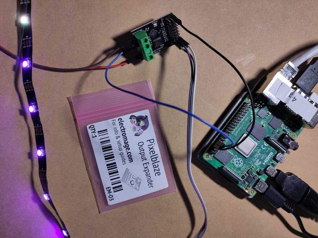
In my search for a good solution to use LED strips with Java, I stumbled on the Pixelblaze Output Expander. This small device is controlled through a serial interface, and handles the control of the LED strip. As it turns out, this is a perfect solution to offload the timing-critical operations from the Raspberry Pi and have reliable output on a LED strip.
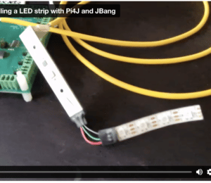
Video Explanation
Based on the created example code and documentation on the Pi4J website, Robert von Burg and I did a live stream to explain the approach and walk through the code.
How LED Strips Work
The LED strips used in the examples of this post, contain LEDs of the WS2812B type, which means they have SMD 5050-LEDs with an integrated IC-driver, so they can be addressed separately.
To control such a LED strip, you need to send it a byte array with RGB (red/green/blue) values. Let's use an example for a strip with three LEDs, on which you want to show:
- Full red (RGB #FF0000)
- Not full white (RGB #A6A6A6)
- Full blue (RGB #0000FF)
Although you may be used to the color ordering RGB for e.g. CSS or in drawing applications, LED strips actually use GRB.
This means, we need a byte array with 9 values:
| Array index | 0 | 1 | 2 | 3 | 4 | 5 | 6 | 7 | 8 |
|---|---|---|---|---|---|---|---|---|---|
| LED | 1 | 2 | 3 | ||||||
| G, R, B | #00 | #FF | #00 | #A6 | #A6 | #A6 | #00 | #00 | #FF |
The IC of the first led will take the first 3 values from the byte array and output the remaining part to the second LED:
| Array index | 0 | 1 | 2 | 3 | 4 | 5 |
|---|---|---|---|---|---|---|
| LED | 2 | 3 | ||||
| G, R, B | #A6 | #A6 | #A6 | #00 | #00 | #FF |
Again, the second LED will take the first 3 values and output the remaining part:
| Array index | 0 | 1 | 2 |
|---|---|---|---|
| LED | 3 | ||
| G, R, B | #00 | #00 | #FF |
For this system to work correctly, a strict timing of the data signal is needed. Otherwise the IC will handle parts of the data as being a new package, and you'll get unexpected results.
About the Pixelblaze
The Pixelblaze is a product created by ElectroMage, with the aim to bring the creation of art, costumes, celebrations, and maker projects to a whole new level. Their two basic components, the "Pixelblaze V3 Standard - WiFi LED Controller" and "Pixelblaze V3 Pico - Tiny WiFi LED Controller" are Wi-Fi-enabled, live-codable LED controllers with a web-based development environment. Fifty light patterns are included, and over 200 more are shared in a community library.
But a third product by ElectroMage is the one that caught my attention to use with a Java application: the "Pixelblaze Output Expander" (PBOE). It is designed to expand output options for the other two Pixelblaze boards, but it can also be driven by just about any other microcontroller or computer over serial UART. The ideal solution for an experiment with Java, JBang and the Raspberry Pi!
Wiring
To control the PBOE, we actually only need one wire to be connected to the Raspberry Pi (RPi) for the serial data to be sent from RPi to PBOE. But we must not forget one important fact: a LED strip with a lot of LEDs will require more power than the RPi can supply.
So we need an external power supply that is dimensioned correctly to provide all the power needed for the strip when all LEDs are at maximum level. As a guideline, 0,1W ~ 0,3W/LED is required per LED. For a strip with 60 LEDs/meter, that means 18W/meter, or a total of 90W for a 5-meter strip.
That's almost 20A at 5V! So, make sure to use an external power supply to power LED strips!!! The 5V of the Raspberry Pi is passed straight through from the USB and the current is therefore limited.
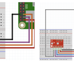
Connections between RPi, PBOE, and power supply:
- GND PBOE to GND power supply, common with GND of RPi
- 5V PBOE to external power supply
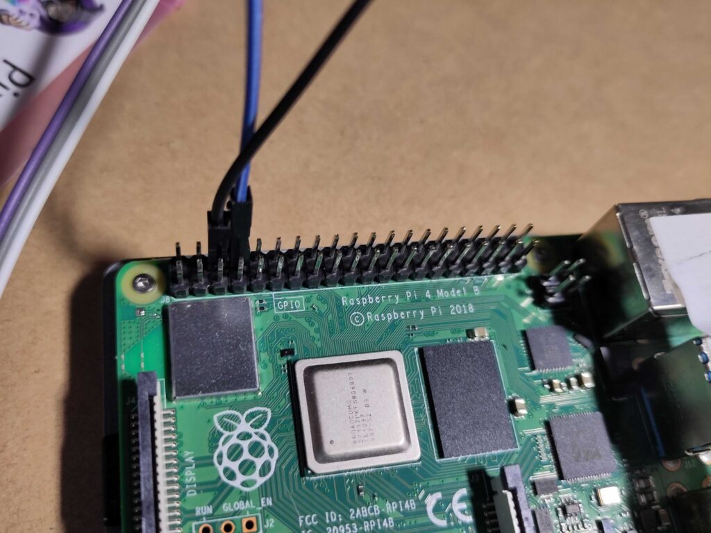
- DAT PBOE to BCM14 on Rpi (pin 8 = UART Tx)
Connections between PBOE and LED strip:
- Din to PBOE Channel 0, Data
- 5V to PBOE Channel 0, 5V
- GND to PBOE Channel 0, GND
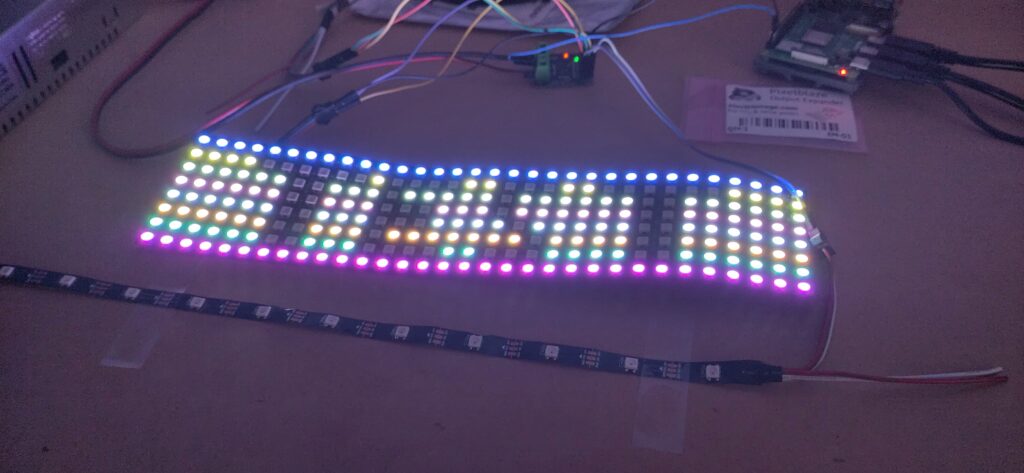
The following pictures show you the connections with one LED strip on channel 0 of the PBOE:
Sample Application
Although the sources used in this post are part of the Pi4J GitHub repository, no Pi4J library is used in this example!
Remember, the Pi4J project is more than just a library, it wants to be the starting point for everyone who wants to experiment with Java and electronics on the Raspberry Pi.
JBang
To simplify the use of the examples, JBang is used, so no full Maven or Gradle project is needed, and the code can be executed with a single command.
On the Pi4J website, a full description is provided with more information about JBang and how to install it on a Raspberry Pi.
PixelBlazeOutputExpanderHelper
The various examples share the same helper-class to send commands to the PBOE. This class takes care of the serial communication between the RPi and the PBOE, hiding most of the "complexity" and provides a few public methods to clear a LED strip or send a byte array with colors.
public PixelBlazeOutputExpanderHelper(String address) {
    System.out.println("Initializing serial");
    adapter = new ExpanderDataWriteAdapter(address);
}

public void sendAllOff(int channel, int numberOfLeds) {
    ...
}

public void sendColors(int channel, byte[] rgbPerPixel, boolean debug) {
    ...
}

public void closePort() {
    adapter.closePort();
}
PixelblazeOutputExpander Example Application
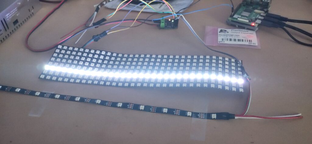
This is the main demo application that is configured to control three different LED strips:
- Channel 0: Strip with 11 LEDs
- Channel 1: Strip with 300 LEDs (5m with 60 LEDs/m)
- Channel 2: Matrix with 256 LEDs (8 rows with 32 columns)
JBang Specific Code
To configure our Java-file to be executable with JBang, we need these extra lines at the start of the file to define the execution with JBang, add the jSerialComm dependency, and include the helper class.
///usr/bin/env jbang "$0" "$@" ; exit $?

//DEPS com.fazecast:jSerialComm:2.10.2
//SOURCES helper/PixelBlazeOutputExpanderHelper.java
Highlight the LEDs One By One
When we look at one of the methods used in this example, we can see how the data is being created to generate a one-by-one effect for a given color mix.
The following approach is taken:
- A loop counts through all the LEDs
- Each time a byte array for the full lenght of the strip is initialized. By default all the values in the byte array or #00, meaning the LEDs will not light up.
- Only the LED for the given loop count will get the given RGB value.
- The byte array is sent to the given channel,
- The thread sleeps for a short moment.
private static void sendOneByOne(int channel, int numberOfLeds,
    byte red, byte green, byte blue) throws InterruptedException {

    System.out.println("One by one on channel " + channel);

    for (int i = 0; i < numberOfLeds; i++) {
        byte[] data = new byte[numberOfLeds * BYTES_PER_PIXEL];
        data[i * BYTES_PER_PIXEL] = red;
        data[(i * BYTES_PER_PIXEL) + 1] = green;
        data[(i * BYTES_PER_PIXEL) + 2] = blue;
        helper.sendColors(channel, data, false);
        Thread.sleep(50);
    }
}
Main Method
I invite you to take a look at the full source code, and will only highlight a few parts here, described in the code comments.
public class PixelblazeOutputExpander {

    // Each LED expects three values for RGB
    // When using RGBW LEDs, this value must be changed to 4
    private static final int BYTES_PER_PIXEL = 3;

    // Channels on which the strips are connected
    private static final int CHANNEL_STRIP_SHORT = 0;
    private static final int CHANNEL_STRIP_LONG = 1;
    private static final int CHANNEL_MATRIX = 2;

    // The length of each strip
    private static final int NUMBER_OF_LEDS_STRIP_SHORT = 11;
    private static final int NUMBER_OF_LEDS_STRIP_LONG = 300; // 60LEDs/m
    private static final int NUMBER_OF_LEDS_MATRIX = 256; // 8*32

    private static PixelBlazeOutputExpanderHelper helper;

    public static void main(String[] args) throws InterruptedException {
        // Initialize the helper by providing the serial address
        helper = new PixelBlazeOutputExpanderHelper("/dev/ttyS0");

        // All off, short LED strip
        helper.sendAllOff(CHANNEL_STRIP_SHORT,
            NUMBER_OF_LEDS_STRIP_SHORT);
        helper.sendAllOff(CHANNEL_STRIP_LONG,
            NUMBER_OF_LEDS_STRIP_LONG);
        helper.sendAllOff(CHANNEL_MATRIX,
            NUMBER_OF_LEDS_MATRIX);
        Thread.sleep(500);

        // One by one red, short LED strip
        sendOneByOne(CHANNEL_STRIP_SHORT, NUMBER_OF_LEDS_STRIP_SHORT,
            (byte) 0xff, (byte) 0x00, (byte) 0x00);

        // Fill strip with random colors, short LED strip
        Random rd = new Random();
        for (int i = 0; i < 5; i++) {
            byte[] random = new byte[NUMBER_OF_LEDS_STRIP_SHORT
                * BYTES_PER_PIXEL];
            rd.nextBytes(random);
            helper.sendColors(CHANNEL_STRIP_SHORT, random, false);
            Thread.sleep(1000);
        }

        ...

        helper.closePort();
    }
}
Executing the Application
No sudo is needed for serial communication with the jSerialComm library, so the application can be started in the terminal with the following command and gives you the output of what is happening with the strips:
$ jbang PixelblazeOutputExpander.java
Initializing serial
Opening /dev/ttyS0
All off on channel 0 with 11
All off on channel 1 with 300
All off on channel 2 with 256
One by one on channel 0, will take 2s
All red
All green
All blue
Random colors 1
..
All red
All off on channel 0 with 11
...
One by one on channel 1, will take 6s
...
All red on LED strip on channel 1
All off on channel 1 with 300
All red on LED matrix on channel 2
...
Closing /dev/ttyS0
Conclusion
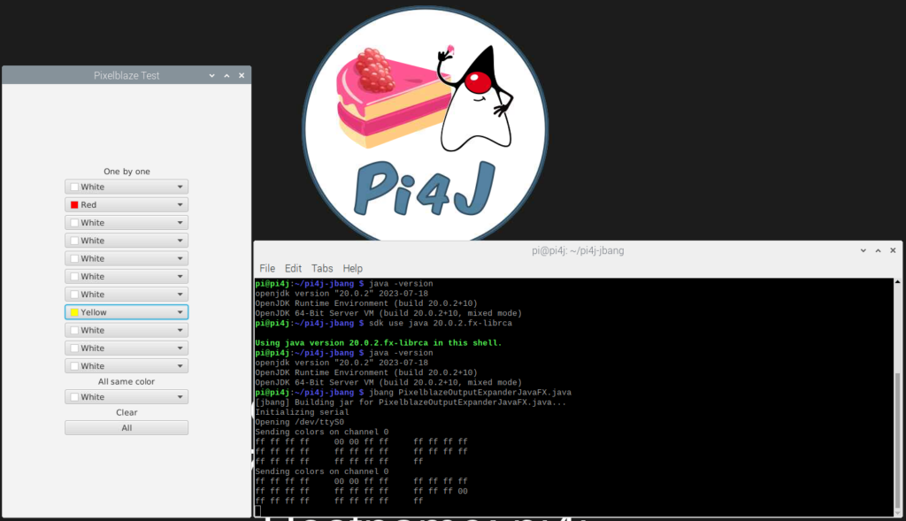
This is only a short introduction, the Pi4J website offers more detailed information and extra examples, including the use of LED matrixes and a JavaFX user interface to define the colors being displayed on a LED strip.
- January 22, 2024
- 7 min read
Frank Delporte is a Java Champion, Java Developer, Senior Technical Writer at Azul, Blogger, Author of "Java Programming for Raspberry Pi - A Hands-On Guide to Electronics and IoT Projects", and Open-Source Contributor for Pi4J, Lottie4J, MelodyMatrix,... Frank writes and talks about Java in business production environments, but also in places people don’t always expect it, on the Raspberry Pi, driving GPIO pins, rendering JavaFX UIs, and running on RISC-V single-board computers.


Comments (0)
No comments yet. Be the first.